
The primary models for characterizing the ESD threshold of an electrical component are the Human Body Model (HBM) and the Charged Device Model (CDM). The main system level EOS models are Pulse, Electrical Fast Transients (EFT), and ESD. There are two sets of ESD standard models, one for components and one for systems. The system model is much more severe than the component model.
Component Level EOS Models
Human Body Model (HBM). The human body is an effective conductor of electricity; we generate static through many common activities such as those shown in the table below. Static electricity generation is also significantly affected by the amount of humidity in the ambient air.
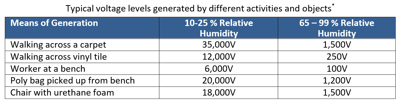
* SOURCE: Fundamentals of Electrostatic Discharge, ESD Association. [Online] 2020. (Retrieved February 8, 2021.).
The HBM model (ANSI/ESDA/JDEC JS-001) is a mathematical representation of what occurs when a charged person contacts an uncharged part or vice versa. The HBM representation is based on an equivalent circuit with a charged 100-pF (picofarad) capacitor in series with a 1500 Ω (ohm) resistor. ANSI/ESDA/JDEC JS-001and JS-002 outline electromagnetic immunity requirements for electronic components when exposed to ESD generated by either human body or metal objects. Learn more about the HBM Immunity Classification Levels.
Charged Device Model (CDM). The CDM is a mathematical representation of a differential charge event between a component and any non-human object charged by triboelectricity or static induction. With the increased use of automation in manufacturing, machines that develop static charges which are not properly grounded can induce charges in nearby devices, which eventually discharge on contact with a conductor.
Contact resistances are typically low in these instances, thus large, extremely short, short-duration currents can occur, for example e.g., 10 Amps for 1-2 nanoseconds. CDM currents are higher than HBM currents because there is no current limiting resistor in the path to limit the discharge. Threshold voltages for CDM are lower than HBM due to these higher currents. There are electromagnetic immunity requirements for electronic equipment due to charged devices. Learn more about the CDM Immunity Classification Levels.
The Component-Level Machine Model (MM). Another model (now discontinued in most standards) is the Machine Model (MM). The MM represents ESD discharge resulting from a differential charge event between a piece of machinery and an electrical component. MM is designed to simulate a machine discharging through a device to ground. The model is based on a 200-pF capacitor and a 0Ω resistor. The MM model is considered similar enough to the HBM model that passing the HBM test implies passing the MM test as well. Therefore, a separate MM rating is no longer required. The technical justification is detailed in JEP172A.
An inductive value is not specified, however most ESD equipment manufacturers place a 450 nH (nanohenries) inductor in the charge path.
System Level EOS Models
IEC 61000-4-2 ESD. The system level ESD test waveform combines CDM and HBM events. It has a fast rise time (1 ns) to a peak current then a fast drop to an HBM type of waveform (Figure 4). The peak of the CDM transient is 3.75 A/kV and the maximum of the HBM component is 2 A/kV. Air discharge level 1 tests are performed at 2 kV and level 4 tests at 15 kV.
IEC 61000-4-4 Electrical Fast Transients (EFT). Electrical Fast Transient (EFT)/Burst events occur on a de-energized power distribution system when an inductive load (such as a relay, switch contactor, or heavy-duty motor) generates a burst of narrow-frequency transients. These fast transients can also be produced by a utility provider swapping in our out their power factor correction equipment. Power line transients can also be caused when an AC power cord is plugged in while equipment is switched off or when circuit breakers or open or closed.
The stress methodology to deal with EFT events is similar to IEC-6100-4-2:2008, except for the repetitive fast transient test. This test consists of bursts of multiple fast transients, coupled into the power supply, control, and signal ports of a piece of equipment. For these tests, the short rise time, repetition rate, and low energy of the transients are significant: test voltages of up to 4 kV (in + and – polarities) are applied to the A/C power leads and up to 2kV is applied to the I/O cables using a coupling clamp. Then test voltages of 5 kHz pulse repetition frequency are applied for 60 seconds to each power supply terminal, including protective earth and every terminal combination.
IEC 61000-4-5 Surge. System Level Surge tests are done to ensure equipment meets requirements for immunity to unidirectional surges caused by over voltages from switching and lightning transients. A surge is applied to the power terminals of the system under test via a capacitive coupling network. The test waveform is a slow but extremely severe pulse.
Comparing ESD/EOS Models
While similar in some ways, ESD events are typically of short duration (measured in nanoseconds, ns), evidencing higher voltages (up to the kV range) and moderate current. EOS events, by contrast, are typically of much longer duration (measured in milliseconds or seconds), with a lower voltage and higher current than ESD. ESD is essentially one subset of EOS phenomena.
CDM and HBM tests are commonly used to test and qualify LED component designs to determine ESD damage threshold levels. Luminus LED components are not factory tested for ESD, because doing so would introduce latent damage to the LED and shorten its service life. Figure 4 shows current waveforms characteristics for HBM, MM, and CDM. The CDM waveform corresponds to the shortest known ESD event and has a rise time of 400 picoseconds with a total duration of ~2 ns.
Similar rise times (i.e., ~10 ns) and total duration for HBM and MM cause comparable joule heating, which results in similar failure mechanisms for both models. The failure signature and discharge processes of the MM test are generally the same as that of the HBM test. Thus, the HBM test can guarantee MM ESD robustness.
If a component design meets minimum requirements for HBM and CDM it will be reasonably robust to discharges during handling and assembly. Compare the waveforms of different component ESD models, shown below:
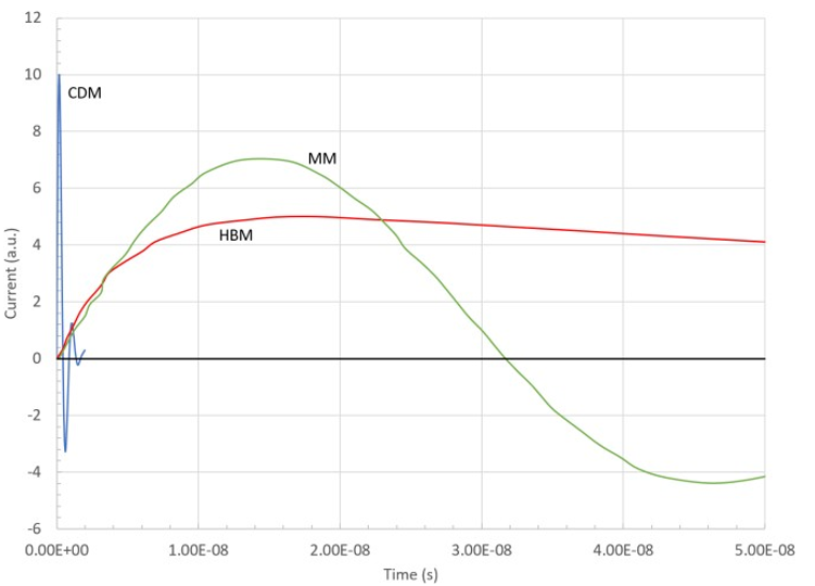
Component level ESD waveforms. The component HBM and component MM models are considered similar enough that only HBM component-level testing is required.
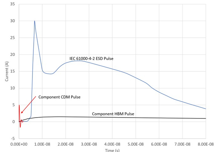
System level ESD test waveform compared to component level waveforms. The IEC 61000-4-2 system ESD test is the least severe pulse in the system level EMC test series.
To learn more about electrical stress and how to prevent damage to LEDs, read the Luminus Application Note: Electrical Stress Damage to LEDs and How to Prevent It
--------------------------------------------------------------------------------------------------------------------
Luminus Website https://www.luminus.com/
Luminus Product Information (datasheets): go to the main page and select Products and then select the type of product you are interested in.
Luminus Design Support (ray files, calculators, ecosystem items: [power supplies, lenses, heatsinks]): go to the main page and select Resources & Tools and select the item you are interested in.
Luminus Product Information sorted by Applications: go to the main page and select Applications.
Where to buy Samples of Luminus LEDs: https://www.luminus.com/contact/wheretobuy.
--------------------------------------------------------------------------------------------------------------------
Technical Support Contact Information: techsupport@luminus.com
Sales Support Contact Information: sales@luminus.com
Customer Service Support Contact Information: cs@luminus.com
Comments
0 comments
Please sign in to leave a comment.