
This article covers the TC measurement method, using a thermocouple combined with information in the Luminus Devices datasheet to estimate LED junction temperature. Refer to APN-001443 Big Chip Thermal Characteristics for additional general information on thermal calculations.
There are many thermal analysis packages that can model the temperature distribution of an LED system design. However, these are expensive, require expertise, and require detailed knowledge of the geometry and materials of each component. This article presents a simple measurement method to estimate the junction temperature and get values good enough for first order calculations.
Measurement Method
We will use the SST-10-FR LED for this example. Please refer to our articles on plot digitization and thermocouple measurements for background material.

LED components are designed to extract heat from the device pn-junction to the bottom of the device where the solder pads are located. This is called the case temperature (Tc) or the solder point temperature (Tsp). There are some other cooling paths like upward convection, but they have minor effects compared to the design-intent heat conduction path from the chip to the solder point.
The strategy for this method is to place a small thermocouple right next to an LED and use the thermal coefficient in the datasheet to estimate the temperature difference between the thermocouple and the LED junction.
The thermal coefficient is in all Luminus datasheets. For this example, it is on page 4 shown below.
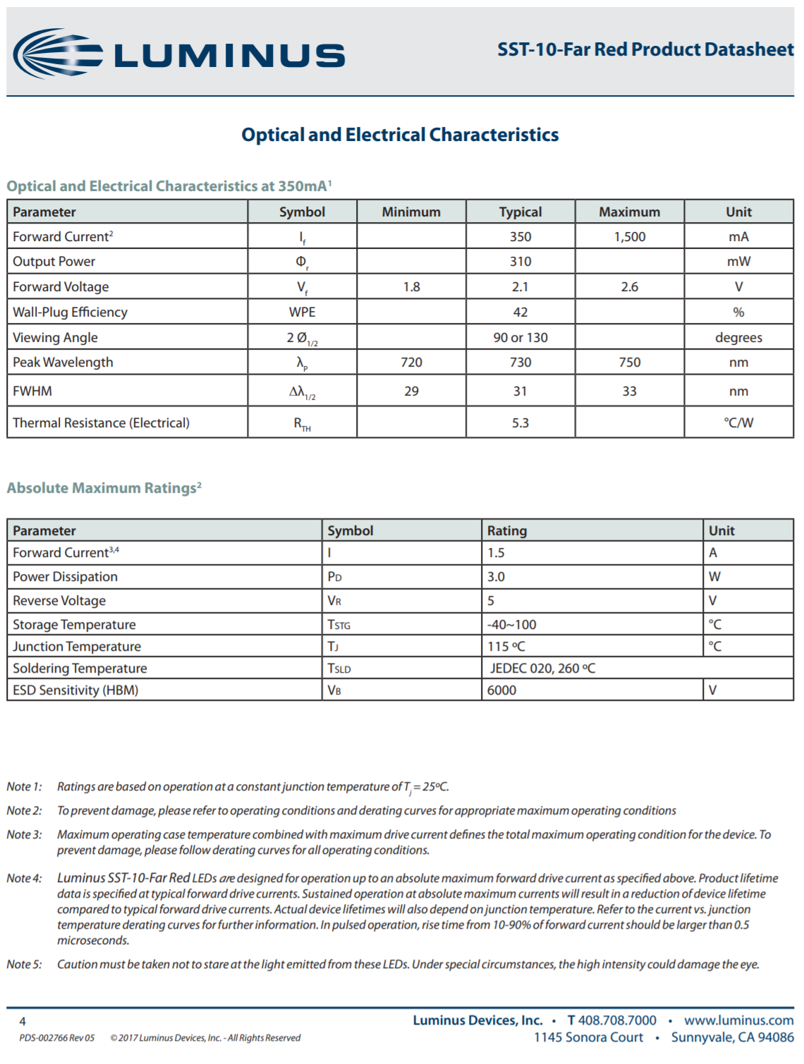
Let's say you use a 350 mA drive current and measure 52 C at your thermocouple point. Then your knowns are:
- Drive Current - 0.35 A
- Nominal Voltage - 2.1 V
- Electrical Input Power - (0.35 A) * (2.1 V) = 0.735 W
- Rth - 5.3 C/W (this is the "electrical" thermal resistance, there is also a "real" thermal resistance which has a more complicated procedure to subtract the LED light power leaving the system and uses a different value for Rth.)
The thermal coefficient is used in this equation
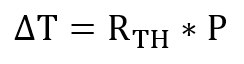
so the temperature difference between the thermocouple and the junction is approximately (0.735 W) * (5.3 C/W) = 3.9 C. If the thermocouple is placed on the copper trace right next to the LED, this is a reasonable number to use for the solder point temperature.
If the thermocouple has to be placed farther from the LED package, we recommend using a thermal camera to determine the temperature offset between the LED and the TC point. This article has recommendations for thermal camera measurements.
Collecting all the information above, we have Tj = (52 C) + (3.9 C) + (2 C) = 57.9 C.
This is a simple example. All the numbers we need are on page 4 of the datasheet and the calculated junction temperature is so far below the 115 C limit that we don't really care about getting more precise numbers.
How about if we drive the LED at 1.5 A, its rated current limit, and still measure 52 C at the thermocouple point?
- Drive Current - 1.5 A
- Estimated Voltage - 2.94 V
- Electrical Input Power - 4.41 W
- Rth - 5.3 C/W
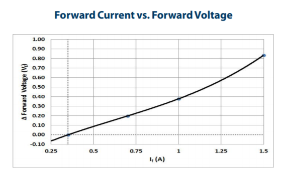
To estimate the voltage at 1.5 A, use the figure on page 5 of the datasheet. If you want more exact numbers, use the methods discussed in our article on plot digitization. Here, I am just going to estimate from the graph and say the increase in forward voltage from the reference point at 350 mA to the new drive current of 1.5 A is about 0.84 V. From the calculation above, we know the nominal voltage at 350 mA is 2.1 V so the voltage at 1.5 A is 2.1 + 0.84 = 2.94 V. Then the electrical input power is 1.5 A * 2.94 V = 4.41 W.
The temperature rise is then 4.41 W * 5.3 C/W = 23.4 C and the junction temperature is 52 C + 23.4 C = 75.4 C. This LED is operating well below the 115 C Tj max limit in the datasheet.
A board temperature of 52 C implies that the heat extraction path at the system level is over engineered and cost can be reduced by redesigning it.
If you want high lumen maintenance, a rule of thumb** is the junction temperature should be below 80% of the Tj max listed in the datasheet, 115 C * 0.8 = 92 C. The temperature rise for the LED is still 23.4 C so the optimal TC point temperature is below 92 C - 23 C = 69 C.
**Luminus has reliability data that can be supplied on request. This is just a simple example so we will use the rule of thumb.
--------------------------------------------------------------------------------------------------------------------
Luminus Website https://www.luminus.com/
Luminus Product Information (datasheets): go to the main page and select Products and then select the type of product you are interested in.
Luminus Design Support (ray files, calculators, ecosystem items: [power supplies, lenses, heatsinks]): go to the main page and select Resources & Tools and select the item you are interested in.
Luminus Product Information sorted by Applications: go to the main page and select Applications.
Where to buy Samples of Luminus LEDs: https://www.luminus.com/contact/wheretobuy.
--------------------------------------------------------------------------------------------------------------------
Technical Support Contact Information: techsupport@luminus.com
Sales Support Contact Information: sales@luminus.com
Customer Service Support Contact Information: cs@luminus.com
Comments
0 comments
Please sign in to leave a comment.