
Measuring the light emitting surface (LES) of an LED package using Thermography presents some challenges. Minimum requirements to get meaningful results are an IR camera with an adjustable emissivity and a procedure for experimental determination of the emissivity of the surface you want to characterize.
“The Ultimate Infrared Handbook for R&D Professionals” has a great deal of detail about thermography theory. Some thermal camera user manuals have a theory section. A good example is this FLIR user manual.
LEDs and PCBs typically have temperatures between room temperature and 150°C which in thermography is considered low-temperature. The best thermal resolution in this range is achieved with long wavelength thermal cameras. For reference, the three most common IR camera types are summarized below.
- Short wavelength – 0.9 to 1.7 μm – Mainly used for imaging, can be used for high-temperature thermography.
- Mid wavelength – 3-5 μm – good for high-temperature thermography, can be used for low temperatures but has less accuracy.
- Long wavelength – 7-12 μm – best for low temperature thermography, also good for high temperatures. Microbolometer technology in this wavelength band is the most common type of moderate cost IR camera.
When using an IR camera, it is best to assume you are collecting information about the temperature of the surfaces in the images. There are a number of factors that will cause errors in the values reported by the thermal camera. These include:
- Emissivity differences of different materials in the field of view
- Reflections of thermal sources behind the camera. Stray reflections from external IR sources are a source of error which needs to be accounted for or minimized. For LEDs, putting a cardboard box over the PCB and imaging through a hole on top is recommended.
- Geometry dependent factors – particularly when imaging holes. Just ignore large temperature differences at holes in the same material. They are not real.
- Angular and distance factors. Always use the same camera position to image test and calibration devices.
- Transmission of thermal energy through the surface material being imaged. This is inevitable when measuring encapsulated LEDs. The chip is the hottest point in an LED package and at least some direct thermal energy is transmitted through the encapsulant.
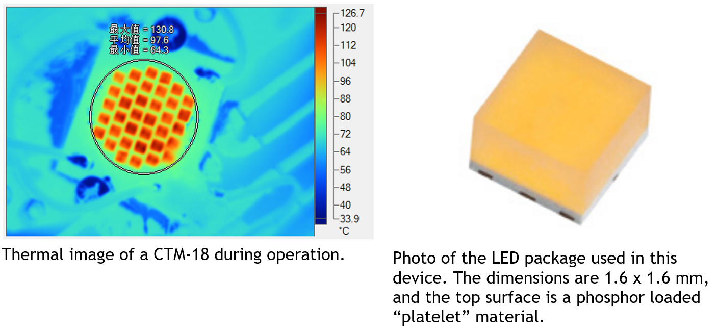
The figure above shows a thermal image of an operating Luminus CTM-18 device. The emissivity of the camera is set at 0.9. This roughly corresponds to the emissivity of the soldermask which has an IR camera temperature that agrees with the thermocouple temperature of 71°C.
Note how cold the camera thinks the metal surfaces are, ~40°C. The actual temperatures of these surfaces are also near 71°C. This LED package structure does not allow for direct measurement of the junction temperature of the LED chip.
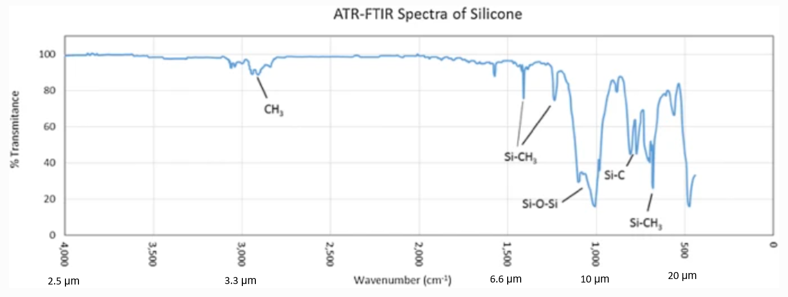
Trying to measure the junction temperature of an encapsulated LED package is exceptionally difficult. Different materials have different absorption in these wavelengths and FTIR measurement of sample coupons is needed to get values. For instance, the thermal radiation emitted by the LED chip is only partially transmitted through silicone which has significant absorption in the 7-12 μm range.
With proper calibration, the surface temperature of each LED package can be determined. The simplest way to calibrate an LED assembly is to image it under near-isothermal conditions, such as when it is unpowered on a hotplate, and adjust the camera emissivity to find values where the camera reports the correct temperature(s) in the region(s) of interest. Some cameras allow the definition of multiple ROIs with a different emissivity assigned for each region while others only have one adjustable emissivity value. This article by Perera and Narendran describes such a calibration in more detail.
It is very common for thermographers to use coatings or stickers with known emissivity to accurately determine the temperature of a surface using IR cameras and this article by Teledyne FLIR discusses some commonly used materials and techniques.
Since LED packages have 3D geometry and the surface of the silicone dome (or platelet) is typically higher than the PCB surface, where is it easy to apply a sticker, it is a good idea to coat a companion control device (or part of the same device if you have room) with a known emissivity material and use that measured temperature value during the hotplate emissivity adjustment process.

Unpowered hotplate calibration process to determine what emissivity values to use in the light up test. The arrows correspond to heat flow when the device is energized.
Note that coating the LES of an LED is not an option for thermal measurements when the LED is energized. The light emission from the LED will drastically heat up any coating and possibly destroy the LED.
--------------------------------------------------------------------------------------------------------------------
Luminus Website https://www.luminus.com/
Luminus Product Information (datasheets): https://www.luminus.com/products
Luminus Design Support (ray files, calculators, ecosystem items: [power supplies, lenses, heatsinks]): https://www.luminus.com/resources
Luminus Product Information sorted by Applications: https://www.luminus.com/applications
Where to buy Samples of Luminus LEDs: https://www.luminus.com/contact/wheretobuy.
--------------------------------------------------------------------------------------------------------------------
Comments
0 comments
Please sign in to leave a comment.