
What are TIMs?
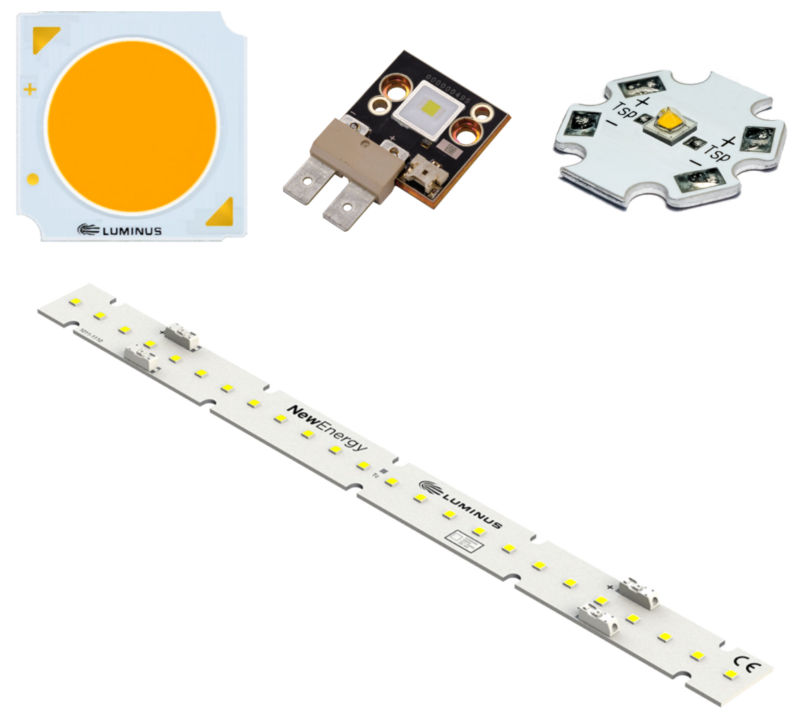
Thermal Interface Materials enhance the flow of heat across (typically metal to metal) interfaces in a thermal stack. Examples are the interface between a Luminus high power device such as the CFT-90, or the interface between an L2 assembly using an MCPCB, or the interface between a starboard, to transmit heat to a heat sink. The TIM fills the gaps in the interface which significantly improves heat conduction across the interface. TIMs are designed to have high thermal conductivity to promote heat conduction into the heat sink. Some TIMs are anisotropic which improves in-plane heat spreading. The figure below shows examples of Luminus products that require TIMs for proper thermal management.
Types of TIMs
There are many different types of TIMs. We will discuss the general types below.
-
Thermal Paste/Grease - This is a thermally conductive material that is spread on one side of the interface before it is joined. It does an exceptional job at filling voids and can have an extremely thin bond line. Thermal grease remains a viscous liquid and when used in volume manufacturing applications, tends to contaminate the workplace over time. Parts must be bolted together since thermal paste has no mechanical strength.
-
Thermal Adhesive - These are typically some form of epoxy with a thermally conductive filler material in the matrix. Metal fillers are used for higher thermal conductivity but the adhesive is then electrically conductive. Ceramic fillers are used to achieve good thermal conductivity and electrical non-conductance. For thin bond lines, you cannot assume electrical isolation since there may be metal-to-metal protrusion contact. There are thermal adhesives that have spacer elements incorporated in the matrix to controls the thickness of the bond line. Thermal adhesives tend to have good mechanical strength. Parts do not have to be bolted together to maintain structural integrity in normal use conditions. It is usually possible to “pop” off a bonded component without damage if rework is required.
-
Thermal Tape - As the name implies, this is a thermally conductive tape that is sold in rolls and sheets. An adhesive is on both sides of the tape so that part scan be assembled by applying pressure. The amount of pressure required is usually stated on the datasheet along with the time it takes for full strength to develop. The thickness of thermal tape is well controlled and is usually part of the part number. Some of the PSA versions of thermal tape have extremely high adhesion. In this case, attempts to dissemble components will usually cause damage.
-
Thermal Pads - Thermal pads usually have low tack (or no) adhesives and are designed to be used in combination with bolts to apply pressure. Thermal pads can be die cut to match the shape of the component mated to the the heatsink. Electrically conductive and nonconductive versions are available. Thermal pads remain solid during operation. The thermal resistance of thermal pads usually has a bolting pressure dependence.
-
Phase Change Materials - Phase change materials are similar to thermal pads in that they are typically sticky die cut solids. The difference is that some of the matrix becomes liquid at a specified temperature and flows out to fill gaps during operation above this temperature.
-
Graphite Pads - Graphite pads are anisotropic with an in-plane thermal conductivity much higher than the through-plane conductivity. This improves heat spreading. Graphite is electrically conductive. Otherwise graphite pads are much like Thermal Pads and need to be bolted down.
The TIM options discussed above gives the designer the following choices:
-
Bolts or no bolts - Compression is needed to fill gaps. Bolts provide continuous compression and part retention. Non bolt designs have a installation pressure specification to fill the gaps and activate the PSA.
-
Electrically conductive or nonconductive
-
Preform or manually cut to size or apply as a paste
-
Thin or thick bond lines
-
Reworkable or not reworkable
Now we will discuss the thermal behavior of TIMs and give a few examples.
Thermal Conduction and Thermal Resistance - Thermal conduction (k) is an intensive material property and is measured in W/m-K. Thermal resistance (Rth) is geometry dependent and is measured in K/W. The relationship between thermal conduction and thermal resistance for a simple slab-type geometry is
Rth = t/kA where t is the thickness and A is the area of the slab.
Rth is used in one dimensional thermal analysis using
dT= P*Rth where dT is the temperature difference across the slab and P is the thermal power in watts.
This analoge to Ohm’s Law can be used in series/parallel combinations to estimate the thermal performance of a system.
By inspection, having a thin bond line and a large area will decrease the Rth in a TIM application but there are practical limits.
Thickness: Using an extremely thin bond line can lead to unanticipated electrical coupling issues in a system. Obviously using an electrically conductive TIM will lead to the heat sink being connected to the MCPCB substrate. What is not obvious is that this will also lead to capacitive coupling through the thin MCPCB dielectric layer to the LED. Thin bond lines can lead to an increased exposure of the LED to electrical transients and possibly random field failures. An electrically non conductive TIM can also have capacitive coupling. This is why dielectric constant values are usually included in thermal pad datasheets. Thin bond lines are good thermally but the system EOS protection strategy needs to be considered in this type of design. See Electrical Stress Damage to LEDs and How to Prevent It for more information.
Area: Using a large area will reduce the thermal resistance but the tricky part is using the correct value of A in the calculation. One dimensional thermal calculations assume that the system components have uniform temperatures at each interface. This simplification is never true and the area used for the Rth calculation needs to be scaled to only consider the effective area in a thermal stack.
An extreme example would be mounting a single 3030 LED (3 mm x 3 mm) on a 1 m2 PCB and heatsink with a 1 m2 TIM between them. Using some typical numbers: k = 5 W/m-K, t = 0.000127 m (5-mils)
Rth(full area) = 0.000127 m / (5 W/m-K * 1 m2) = 0.0000254 K/W, way too low and
Rth(LED_area) = 0.000127 m / (5 W/m-K * 9e-6 m2) = 2.82 K/W which is closer to the true value but too high since there is some heat spreading in the MCPCB.
How should you estimate the area without using a full FEM analysis? There is a method called 2D thermal analysis that predates computer solutions and provides some guidance. Many good discussions of the 2D shape factor technique can be found on the internet using search tools.
The most simplistic shape factor solution is to assume that the effective length, L, doubles in each layer so the area increases by a factor of (2L) 2. So for an LED with area A mounted on an MCPCB mounted on a TIM, the area used for the TIM Rth calculation is 4 time the area of the LED package. This gives
Rth(shape_factor_area) = 0.000127 m / (5 W/m-K * 4 * 9e-6 m2) = 0.71 K/W
This method is simplistic and provides an order of magnitude solution. Note that there is no factor for the void percentage so this estimation is optimistically assuming perfect contact. If more precise values are needed, we recommend full FEM analysis performed by someone expert in this method.
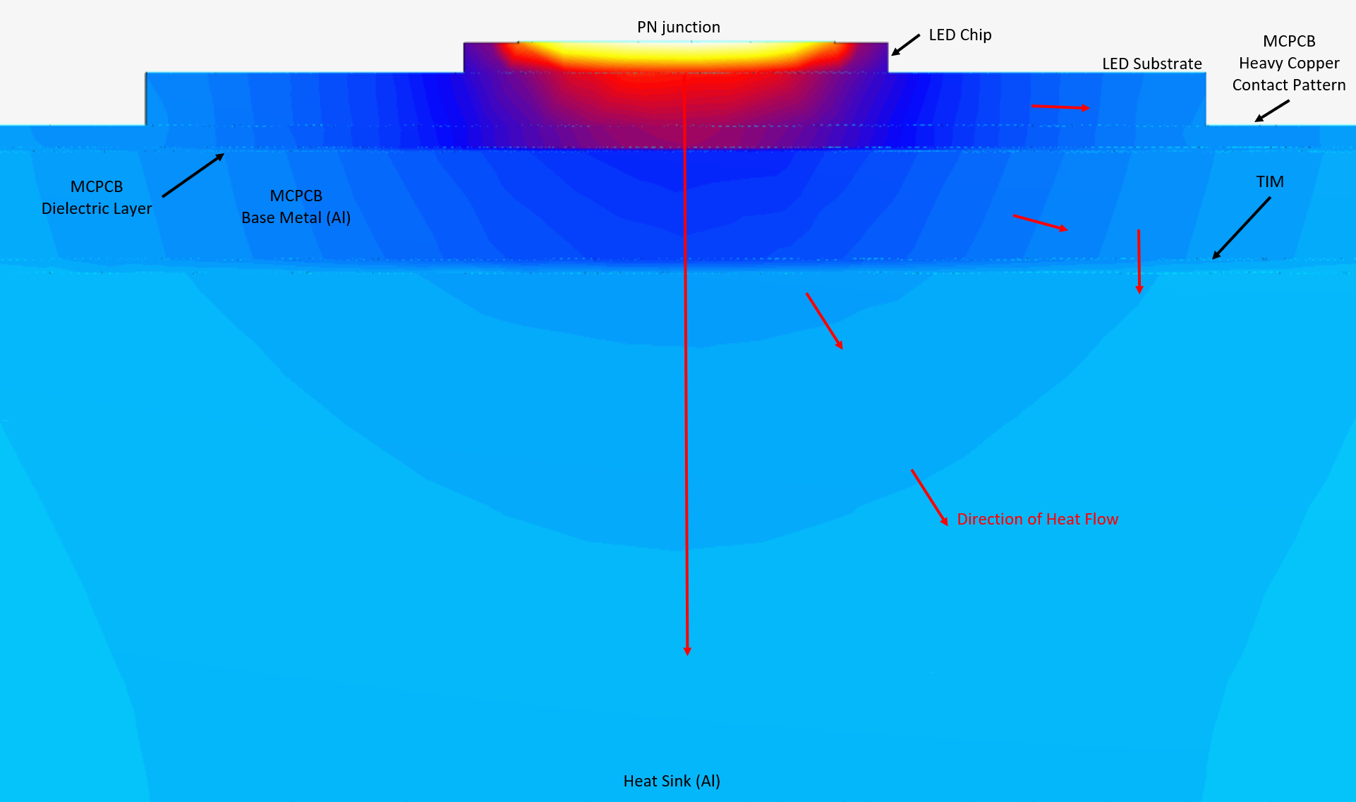
Thermal Spreading: Typical applications sandwich a TIM between two metals, usually aluminum or copper. The thermal conductivity of typical TIMs range from 1 - 15 W/m-K, which is extremely low compared to copper and aluminum that have nominal thermal conductivity values of 398 W/m-K and 235 W/m-K respectively. TIMs are also typically much thinner than the MCPCB and the heat sink structures. These two factors combine to inhibit in-plane heat spreading inside the TIM compared to the metal layers. The figure below visualizes this phenomenon. Heat flow is always perpendicular to isotherms and the red arrows below indicate these directions in the thermal stack layers. Heat flow through the TIM (and the MCPCB dielectric) is vertical with parallel isotherms while the layers above and below the TIM show significant in-plane heat spreading. For the same thickness, a low conductivity TIM has more thermal spreading above it in the thermal stack.
Datasheets: Most thermal pad data sheets have the thermal conductivity of the material in W/m-K and a table of precalculated Rth values based on available thickness, compression factors, and are normalized by area.
So for instance, we might see
Thermal conductivity = 5 W/m-K
For a 40-mil test sample,
at 10% compression = Rth = 0.41 K-in2/W
at 20% compression = Rth = 0.34 K-in2/W
at 30% compression = Rth = 0.3 K-in2/W
where you need to pick a compression case (often expressed in kPa) and scale these values by dividing by your estimate of the effective area. There is no standard for these data, so be prepared to do a lot of unit conversion. Guidance on the relationship between torque values and TIM compression can be found in the Luminus Help Center Article “What size screw and torque should I use for a Luminus core board product with a compressible TIM?”.
--------------------------------------------------------------------------------------------------------------------
Luminus Website https://www.luminus.com/
Luminus Product Information (datasheets): https://www.luminus.com/products
Luminus Design Support (ray files, calculators, ecosystem items: [power supplies, lenses, heatsinks]): https://www.luminus.com/resources
Luminus Product Information sorted by Applications: https://www.luminus.com/applications
Where to buy Samples of Luminus LEDs: https://www.luminus.com/contact/wheretobuy.
--------------------------------------------------------------------------------------------------------------------
Technical Support Contact Information: techsupport@luminus.com
Sales Support Contact Information: sales@luminus.com
Customer Service Support Contact Information: cs@luminus.com
Comments
0 comments
Please sign in to leave a comment.